Inflatable Door Seals for Aerospace Ground Test Facilities
Controlled contact around large access door frames in jet engine ground test cells. Seal installation is assessed together with door stiffness, closed clearance, pressure differential and the operating sequence.
Explore inflatable seal and mounting options that provide contact around access door frames in jet engine test cells.
Engine test cells
Test chamber doors
Pressure test compartments
Key factors in profile selection
Door opening and contact direction
Pressure differential and acoustic requirements
Mounting tolerances and operating cycle
APPLICATION DETAILS
Equipment and sealing applications
Explore the equipment, the joint where the seal works and manufacturing options for your application.
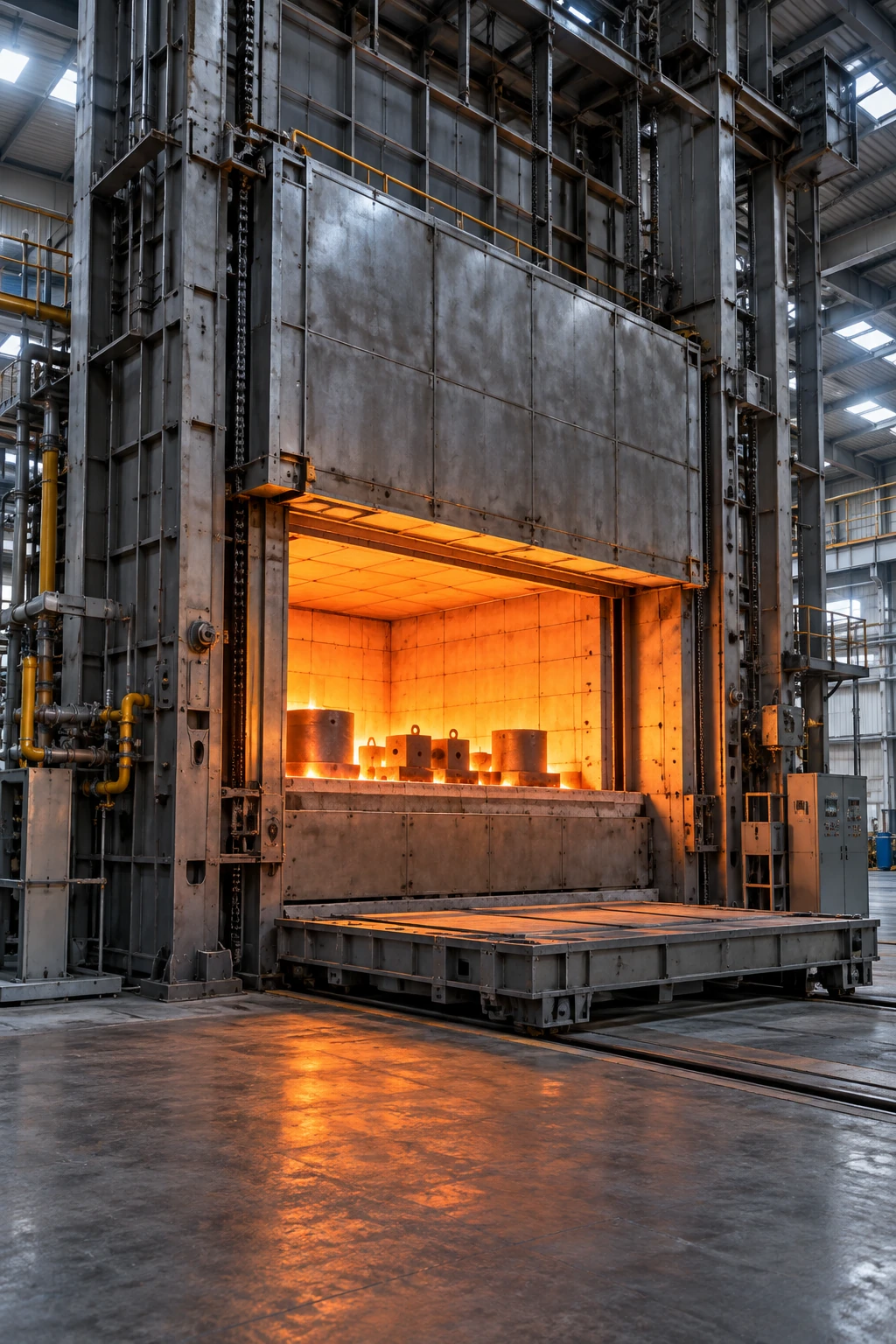
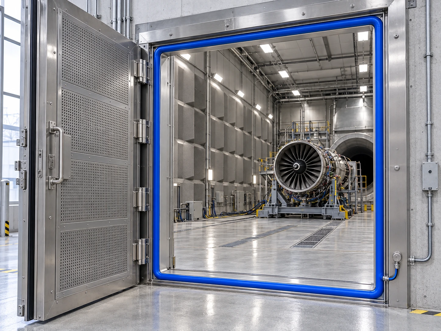
Enlarge image ↗Seal location: Fixed access-door frame of the ground-test chamber
01 / EQUIPMENT AND PURPOSE
Jet engine ground-test cells
Perimeter sealing at the test chamber access door.
A ground-test cell supports engine testing within a controlled facility. The large access door opens for engine handling and maintenance and is mechanically secured during testing.
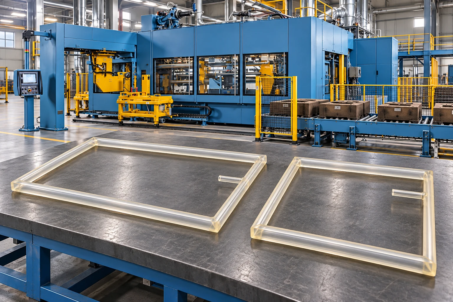
The inflatable seal works between the access door and fixed test-cell frame. The illustrated loop belongs to that door joint; it is not a component fitted to the engine fan or air intake.
Benefits of the seal
Enclosing the joint. Helps limit unwanted air passage around the access door.
Wide service access. The vented profile releases the clearance required for door movement.
Controlled operating sequence. Closed and locked door status, seal pressure and venting are considered together.
Our manufacturing solution
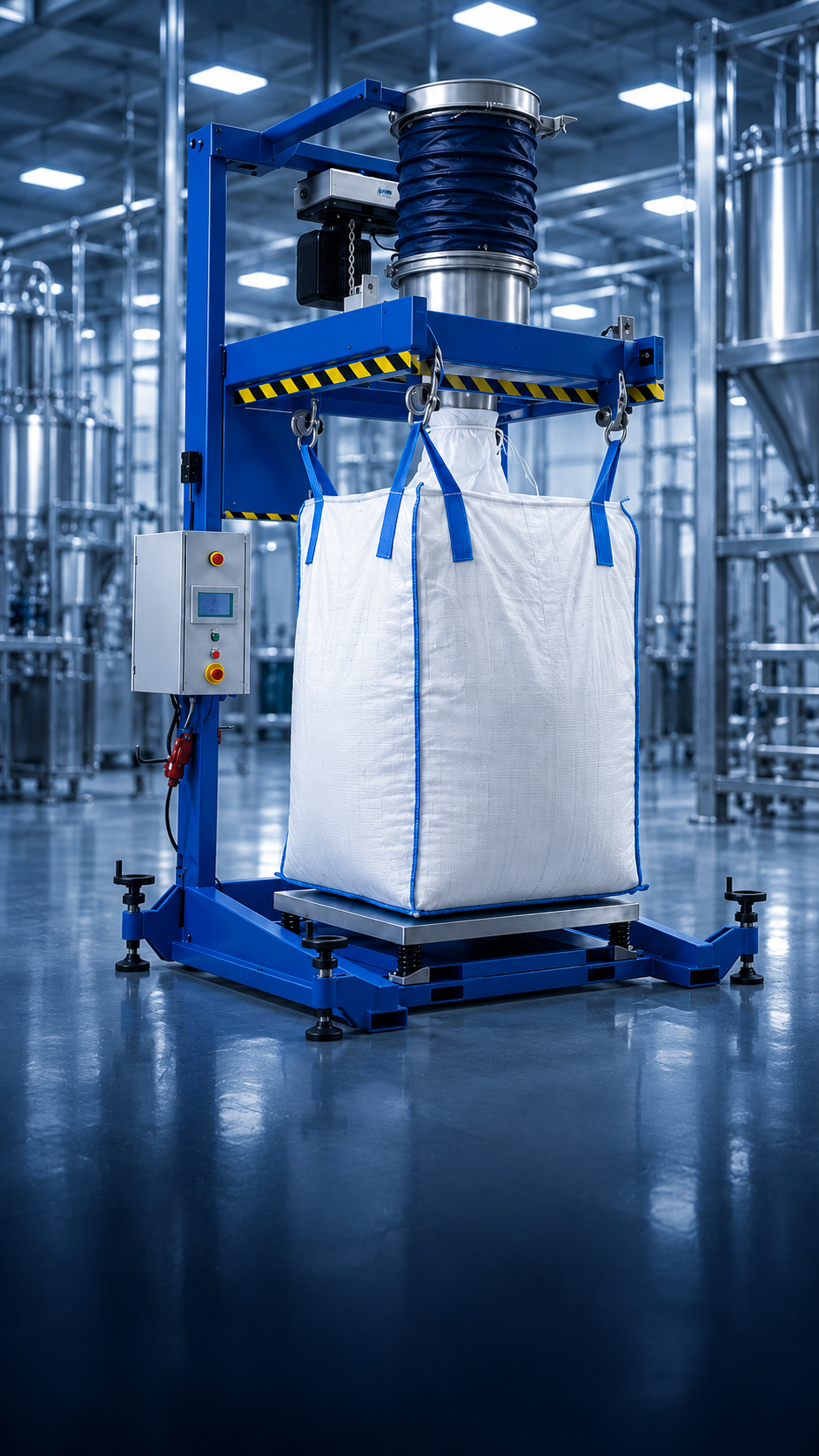
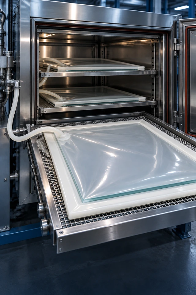
We manufacture custom inflatable seals for this type of equipment. We assess the section, closed-loop dimensions, corner radii and air inlet arrangement against your drawing, and select the material for the temperature, product contact and cleaning conditions.
Selection and installation details
Provide test-cell pressure differentials and acoustic targets.
Measure door rigidity, lock positions and the perimeter gap.
Define material, traceability and testing requirements for the ground-test equipment at project outset.
Images are representative application designs, not photographs of customer installations. The final profile, material and operating values are established during project review.
PREPARING YOUR PROJECT
What information is needed for selection?
Technical drawings and photographs of the existing installation help us assess the profile and connection options together. Include the following information with your enquiry.
Application-specific selection information
Information to provide
Assessment details
Facility and door layout
Test cell purpose, door dimensions, movement and locking points.
Operating conditions
Pressure differential at the joint, actual temperature, cycle frequency and contact media.
Geometry and controls
Frame stiffness, perimeter clearance, groove section, valve position and pressure monitoring needs.
Acceptance criteria
Leakage and acoustic targets, material traceability and facility validation requirements.
Frequently asked questions
Is the solution shown here an aircraft component?
The examples concern fixed access doors in ground test facilities. Applications on flight equipment require a separate technical specification and conformity assessment.
Can an acoustic rating be assigned to the seal alone?
Acoustic performance is assessed with the door, walls, locking arrangement and other transmission paths. Facility performance cannot be specified from the seal alone without testing the final assembly.
Which drawing is needed for a quotation?
Provide a closed door-to-frame section showing perimeter clearance, groove dimensions and the air connection position, together with pressure differential and cycle information.
Catalogue & technical resources
Explore the related catalogue and review profile and installation options alongside your application drawing.

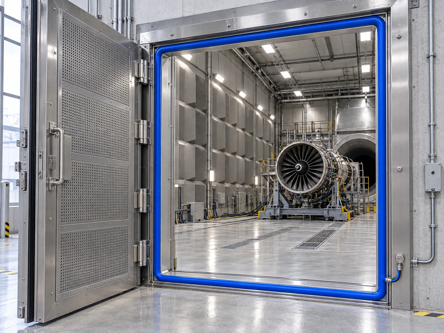 Enlarge image ↗