Explore the equipment, the joint where the seal works and manufacturing options for your application.
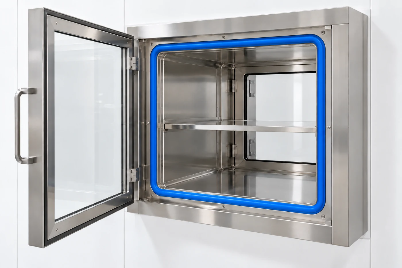
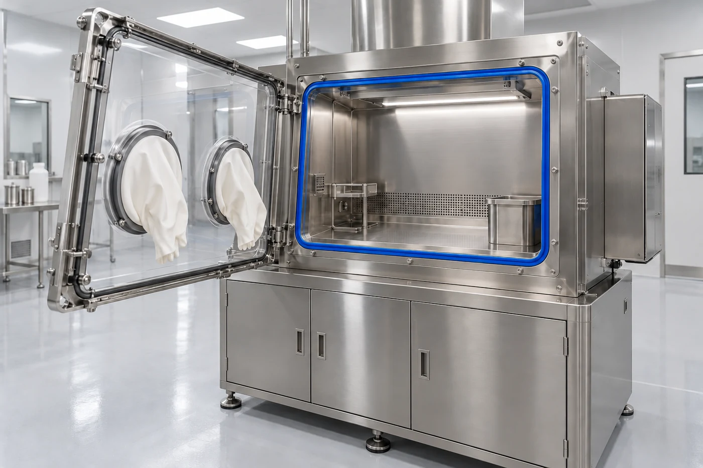
Enlarge image ↗Seal location: Perimeter channel between the front access panel and fixed opening
01 / EQUIPMENT AND PURPOSE
Glove-port isolator
Controlled sealing around a large access panel.
A glove-port isolator provides an enclosed volume for activities such as weighing, sampling or material preparation. Operators handle the product through gloves fitted to the panel.
An inflatable seal is retained in a suitable channel around the opening access panel or fixed aperture. The blue loop in the illustration surrounds the fixed aperture and establishes perimeter contact when the panel closes. The glove cuff and glove-port ring form a different joint.
Benefits of the seal
Enclose the working volume. Limiting leakage paths around the panel contributes to enclosure integrity.
Wide service access. Venting retracts the seal and allows the panel to open.
Contact after closure. Contact is established pneumatically.
Our manufacturing solution
We manufacture custom inflatable seals for this type of equipment. We assess the section, closed-loop dimensions, corner radii and air inlet arrangement against your drawing, and select the material for the temperature, product contact and cleaning conditions.
Selection and installation details
Include glass or transparent-panel deflection, locking points and closure tolerance in the sealing-gap assessment.
Select the profile for the product, cleaning liquid and any hydrogen peroxide decontamination cycle.
Design the channel for cleaning access and reduced product accumulation. Assess the splice and corners separately.
Define separate inspection and maintenance records for the main panel, transfer door and glove components.
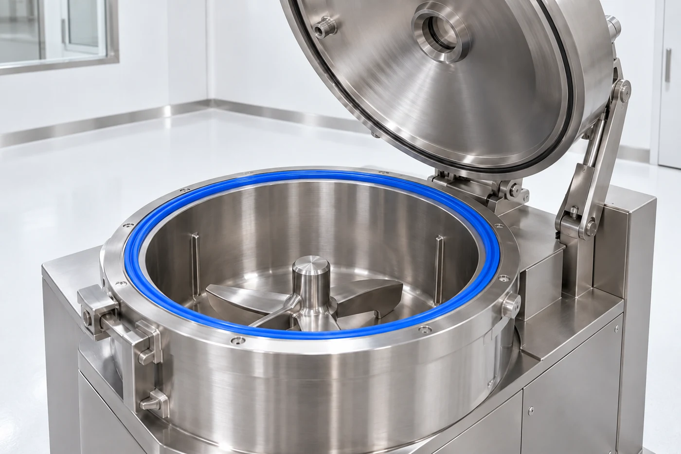
Enlarge image ↗Seal location: Perimeter joint between the vessel rim and lid
02 / EQUIPMENT AND PURPOSE
RMG high-shear granulator
Perimeter contact at the mixing-vessel lid.
An RMG mixes powders under high shear and supports wet granule formation when binder liquid is added. The main impeller moves the product bed; a chopper controls agglomerates as required by the process.
In a suitable equipment design, an inflatable seal is retained in a perimeter channel at the vessel mouth or in a lid retainer. The illustration shows the loop around the fixed vessel opening. After mechanical closure, the profile contacts the lid surface.
Benefits of the seal
Limit dust passage. The profile helps reduce the leakage path around the lid.
Maintain a closed process joint. Repeatable contact between lid and vessel supports closure under the defined operating conditions.
Access for cleaning and changeover. Releasing the air retracts the profile so the lid can open.
Our manufacturing solution
We manufacture custom inflatable seals for this type of equipment. We assess the section, closed-loop dimensions, corner radii and air inlet arrangement against your drawing, and select the material for the temperature, product contact and cleaning conditions.
Selection and installation details
Assess lid stiffness, locking force and vessel-mouth gap around the full perimeter.
Specify product powder, binder, solvents and WIP/CIP cleaning media together for material selection.
Protect the inflation connection from lid movement and product exposure without interrupting channel continuity.
Specify any process vacuum or pressure separately from inflation pressure. Equipment structural strength is a separate design requirement.
Enlarge image ↗Seal location: Ring between the removable product bowl and upper body
03 / EQUIPMENT AND PURPOSE
Fluid-bed dryer / processor
Controlled sealing at a removable bowl interface.
Conditioned air passes through a distributor and moves the powder or granule bed. An FBD is used for drying; suitable FBP arrangements can also perform granulation or coating with spray equipment.
An inflatable seal can be used at the perimeter joint where a removable product bowl meets the upper body. The illustration shows the blue loop on the underside of the upper section with the bowl separated. Depending on equipment design, filter or other body interfaces may have separate seals.
Benefits of the seal
Support the intended air path. Limiting unwanted leakage at the interface helps manage air through the designed inlet, product bed and outlet path.
Contain product dust. Closing the perimeter gap can contribute to reducing dust passage into the working area.
Bowl change and cleaning access. Within a suitable clearance, the deflated profile allows bowl separation.
Our manufacturing solution
We manufacture custom inflatable seals for this type of equipment. We assess the section, closed-loop dimensions, corner radii and air inlet arrangement against your drawing, and select the material for the temperature, product contact and cleaning conditions.
Selection and installation details
Assess bowl lifting, centring and the closed-position gap together. The seal is not a bowl support component.
Specify hot process air, product dust, solvents and cleaning cycles for the profile material and splice.
Make the channel and mating surface accessible for inspection and removal of dust deposits.
Assess body alignment and the bowl-lift lock to maintain the defined contact range around the full perimeter.
Enlarge image ↗Seal location: Perimeter between the drum access door and fixed housing
04 / EQUIPMENT AND PURPOSE
Tablet coating equipment
A perimeter barrier at the drum access door.
A tablet coater moves tablets in a rotating drum while spraying coating liquid. Conditioned process air supports liquid removal and formation of the coating layer.
In suitable coater configurations, inflatable seals are used around front viewing/access doors or side service doors. The illustration shows the blue loop around a fixed circular access opening, with the drum inside. The seal contacts the mating surface after the door closes.
Benefits of the seal
A barrier around the access door. The seal contributes to limiting passage of air, dust and aerosols at the joint.
Access between batches. Venting retracts the profile.
Repeatable perimeter contact. Once the door is positioned correctly, pneumatic expansion establishes a continuous contact line within the specified gap.
Our manufacturing solution
We manufacture custom inflatable seals for this type of equipment. We assess the section, closed-loop dimensions, corner radii and air inlet arrangement against your drawing, and select the material for the temperature, product contact and cleaning conditions.
Selection and installation details
Include aqueous or solvent-based coating liquids and cleaning agents in material assessment.
Check channel continuity and profile retention around circular or radiused openings.
Keep the seal clear of the drum, nozzles and door movement; allow access for residue removal.
Assess door deflection, locking points and temperature-dependent gap changes against the selected inflation range.
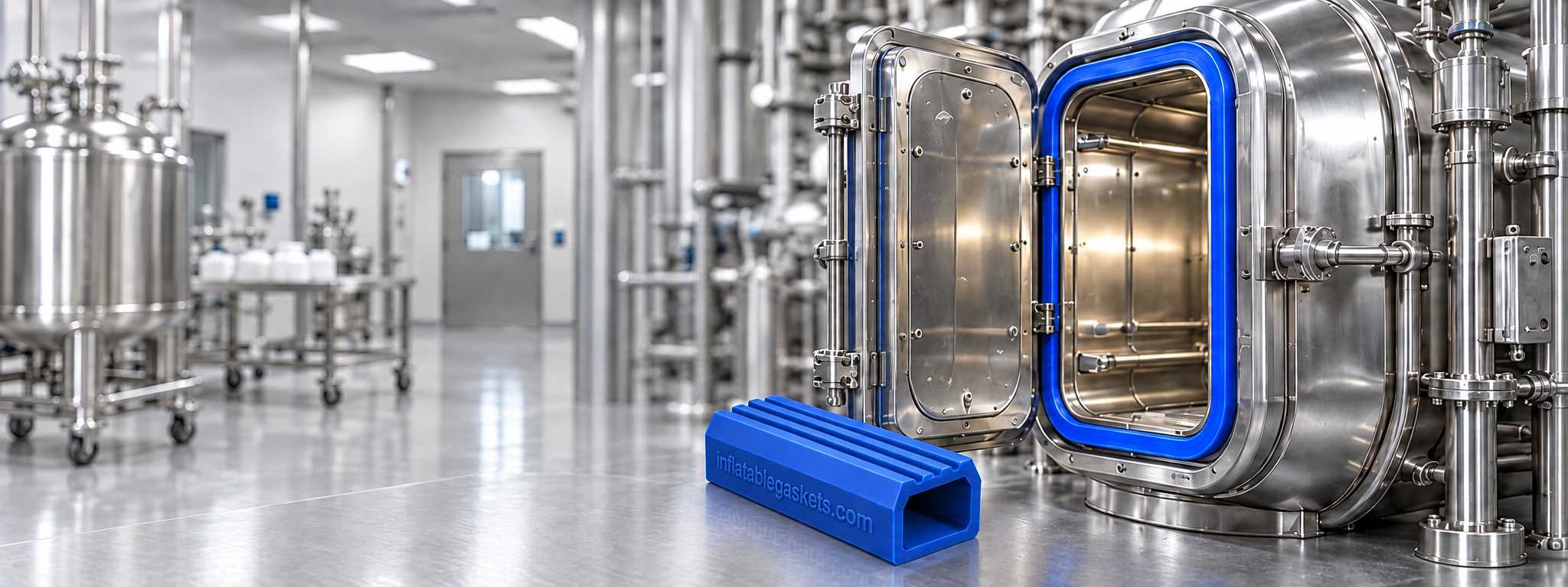
Enlarge image ↗Seal location: Sealing path between the door and pressure-vessel body
05 / EQUIPMENT AND PURPOSE
Medical steam sterilizer
Door contact suited to the temperature and pressure cycle.
A steam sterilizer processes suitable loads through a defined cycle. Air removal, saturated-steam exposure, pressure changes and drying are arranged for the equipment and load type.
In a suitable door arrangement, an inflatable seal sits in a channel around the chamber aperture and contacts the closed door surface. The illustration shows the door open to reveal the perimeter loop. Select the section for the inflation medium, temperature and door geometry of the specific equipment.
Benefits of the seal
Seal the chamber joint. The profile contributes to limiting leakage around the door.
Manage door movement. After suitable chamber conditions are established at cycle end, the profile can retract.
Planned inspection and replacement. An accessible channel and profile arrangement simplify perimeter inspection.
Our manufacturing solution
We manufacture custom inflatable seals for this type of equipment. We assess the section, closed-loop dimensions, corner radii and air inlet arrangement against your drawing, and select the material for the temperature, product contact and cleaning conditions.
Selection and installation details
Specify steam exposure, temperature, pressure/vacuum cycling and operating frequency together for material selection.
The inflation gas or medium follows the manufacturer design; this catalogue does not assign one common pressure setting.
Assess channel finish, drainage, corners and temperature-dependent gaps. Use lubricants only as allowed by the equipment instructions.
Manage door locking, pressure-chamber design and opening interlocks according to the equipment manufacturer design.
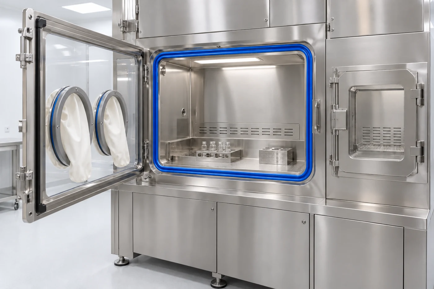
Enlarge image ↗Seal location: Access-panel perimeter of the protected working chamber
06 / EQUIPMENT AND PURPOSE
Radiopharmaceutical isolator
A perimeter barrier around access openings in a protected volume.
A radiopharmaceutical isolator organizes preparation, vial or syringe filling and dose operations within a controlled working volume. Its protective approach combines shielding, air management, filters, transfer compartments and remote or glove-port handling.
Inflatable seals may surround the main access aperture and suitable transfer-chamber doors. The blue loop in the illustration follows the fixed main aperture. Contact is established after the opening is closed and mechanically retained.
Benefits of the seal
Support the controlled volume. Limiting leakage around openings helps maintain the defined air and pressure regime.
Manage transfers. Door position and seal-pressure monitoring can be included in compartment transfer sequences.
Service access. Once the seal is vented, the relevant access panel can open.
Our manufacturing solution
We manufacture custom inflatable seals for this type of equipment. We assess the section, closed-loop dimensions, corner radii and air inlet arrangement against your drawing, and select the material for the temperature, product contact and cleaning conditions.
Selection and installation details
Specify process media, cleaning/decontamination chemicals and possible radiation exposure separately for material assessment.
Assess shielded-panel weight and hinge behaviour with the closed-position gap and locking arrangement.
Control main-volume and transfer-compartment seals separately for their pressure regime and opening sequence.
Locate connections and hoses in protected, service-accessible positions, clear of closing surfaces.
Images are representative application designs, not photographs of customer installations. The final profile, material and operating values are established during project review.
Perimeter loop centred on the thickness edge of the stainless steel door leaf
CLEANROOMS
Continuous door sealing for controlled environments.
Let us select a profile and mounting solution that provides even contact around cleanroom and airlock door frames.
The blue seal in the illustration follows the narrow thickness edge of the stainless steel door leaf and is centred on that surface. When the door closes, it expands towards a suitable frame surface. Frame-mounted channel arrangements are also possible.
Benefits of the seal
A controlled perimeter barrier. The seal helps limit unwanted air passage through the leaf-to-frame gap.
Easier opening and closing. Within a suitable gap, the deflated profile retracts clear of the movement path.
Orderly, accessible mounting. Planning the channel and inflation connection protects the profile and provides access for inspection and replacement.
Our manufacturing solution
We manufacture custom inflatable seals for this type of equipment. We assess the section, closed-loop dimensions, corner radii and air inlet arrangement against your drawing, and select the material for the temperature, product contact and cleaning conditions.
Selection and installation details
Measure leaf thickness, closed-position gap and mating surface at the top, bottom and both sides. Centre the seal on the contact line defined in the drawing.
Match the corner radii of the leaf and frame. Avoid profile kinking or restriction of the internal air path at corners.
Protect the inflation connection and hose outside the hinge movement and closing contact surfaces.
Specify cleaning agents, access frequency and any decontamination conditions together for material selection.
Enlarge image ↗Seal location: Leaf-to-frame joint around the inlet and outlet doors
02 / EQUIPMENT AND PURPOSE
VHP transfer chamber
A perimeter barrier suited to the decontamination cycle.
A VHP transfer chamber moves materials between areas with different cleanliness requirements. After loading and door closure, a defined surface decontamination cycle is performed.
Inflatable seals are used around the inlet and outlet doors. The illustration shows a blue loop at the front fixed aperture and a second door opposite. Once the door is locked, the seal closes the contact line between leaf and frame.
Benefits of the seal
Support the cycle environment. Limiting leakage at door joints helps manage decontamination vapour within the intended volume.
Separate adjoining areas. Controlling perimeter contact and the opening sequence of both doors supports the management of direct passage between areas during transfer.
Access for repeated transfers. The profile retracts before opening.
Our manufacturing solution
We manufacture custom inflatable seals for this type of equipment. We assess the section, closed-loop dimensions, corner radii and air inlet arrangement against your drawing, and select the material for the temperature, product contact and cleaning conditions.
Selection and installation details
Specify peroxide concentration, exposure duration, temperature and possible condensation for material assessment.
Plan separately monitored air lines, lock information and seal pressure status for each door.
Assess radiused corners, the splice and inflation connection against the gas-tightness target.
Keep the seal path clear of shelves, handles and transfer movement, while preserving cleanable surfaces.
Images are representative application designs, not photographs of customer installations. The final profile, material and operating values are established during project review.
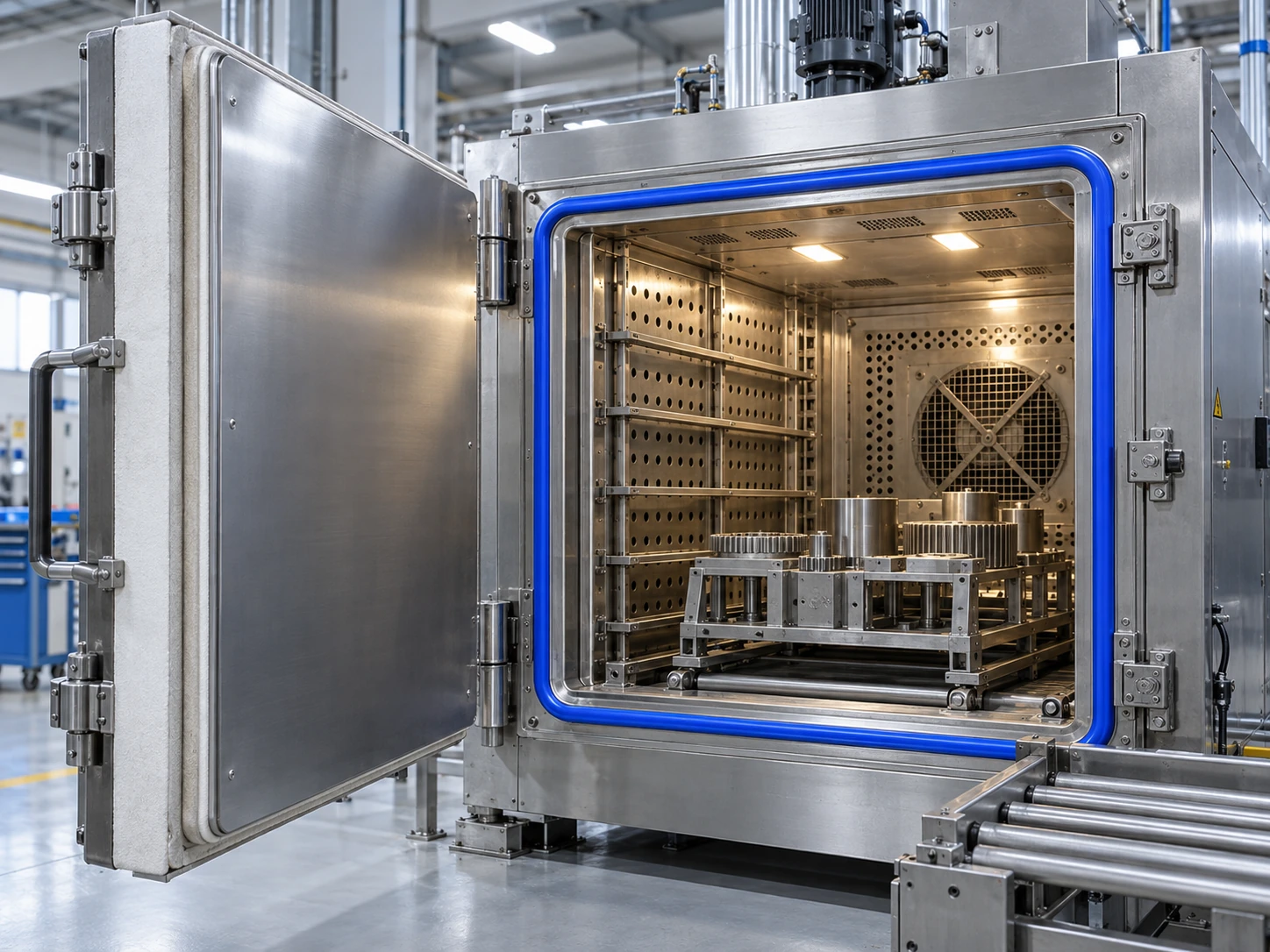
Seal around the door of an insulated process oven
INDUSTRIAL OVENS
Door sealing solutions for thermal processes.
Explore sealing options for oven and process cabinet doors based on the temperature at the seal and the mounting conditions.
Explore the equipment, the joint where the seal works and manufacturing options for your application.
Enlarge image ↗Seal location: Perimeter channel between the insulated door and fixed frame
01 / EQUIPMENT AND PURPOSE
Process ovens and drying cabinets
Controlled contact at the door joint of a thermal process chamber.
Process ovens and drying cabinets treat products with a defined temperature and airflow. The loading and service door remains closed during the process.
The seal works in a channel at a door-to-frame joint where suitable temperature conditions are provided. The oven process temperature and the actual temperature at the seal are assessed separately.
Benefits of the seal
Perimeter contact. Helps limit unwanted air passage through the door joint.
Service access. Venting retracts the profile to release the door movement.
Geometry-specific selection. Thermal expansion and the closed gap inform the profile and holder design.
Our manufacturing solution
We manufacture custom inflatable seals for this type of equipment. We assess the section, closed-loop dimensions, corner radii and air inlet arrangement against your drawing, and select the material for the temperature, product contact and cleaning conditions.
Selection and installation details
Provide continuous and short-term temperatures at the seal.
Assess thermal expansion, insulation clearance and mating surfaces around the perimeter.
Protect the air inlet and tubing from hot surfaces.
Images are representative application designs, not photographs of customer installations. The final profile, material and operating values are established during project review.
Channel around the fixed opening and the mating surface of the closed leaf
MARINE
Door and hatch sealing for marine conditions.
Let us assess inflatable seals that conform to the mounting surface on yacht doors, garage hatches and service openings.
Explore the equipment, the joint where the seal works and manufacturing options for your application.
Enlarge image ↗Seal location: Channel around the fixed opening and the mating surface of the closed leaf
01 / EQUIPMENT AND PURPOSE
Sliding saloon doors
Protect interior comfort at the transition to the open deck.
Used on glazed sliding doors between the aft cockpit or seating deck and the saloon. The opening allows frequent access while the yacht is at anchor; when closed, the door forms the boundary between the interior and the outside environment.
The seal is installed in a suitable channel around the fixed frame. Once the door leaf reaches its final position and is mechanically secured, the profile inflates against the mating surface. Before opening, the air is vented so the leaf can move along its track.
Benefits of the seal
Interior protection. Helps limit rainwater and deck wash water passing through the perimeter joint.
Greater comfort. Reducing perimeter air leakage can help reduce draughts and wind noise caused by leakage paths.
Smooth movement. Retraction of the deflated profile reduces rubber contact during sliding.
Our manufacturing solution
We manufacture custom inflatable seals for this type of equipment. We assess the section, closed-loop dimensions, corner radii and air inlet arrangement against your drawing, and select the material for the temperature, product contact and cleaning conditions.
Selection and installation details
Track alignment, sill drainage and lock position are checked together. The seal must remain clear of the moving track components. Clean drainage channels and sills are an essential part of the complete installation.
Confirm that the seal has released around the full perimeter before sliding the door.
Enlarge image ↗Seal location: Channel around the fixed opening and the mating surface of the closed leaf
02 / EQUIPMENT AND PURPOSE
Side-deck access doors
Controlled sealing for sliding access along a narrow side deck.
Suitable for doors connecting a yacht's side deck to the saloon, a service passage or an enclosed living space. In a narrow walkway, a sliding leaf avoids the need for a large outward swing area.
The perimeter seal sits inside the fixed frame. Horizontal door travel and seal inflation take place at different stages. The deflated profile provides clearance; air is supplied only when the door is fully closed and locked to establish perimeter contact.
Benefits of the seal
Protection from exposure. Helps restrict rain and spray entering through the side-deck door joint.
Compact installation. A profile retained within a channel provides an orderly arrangement around the frame.
Service access. Accessible air inlets and retainers simplify inspection and seal replacement.
Our manufacturing solution
We manufacture custom inflatable seals for this type of equipment. We assess the section, closed-loop dimensions, corner radii and air inlet arrangement against your drawing, and select the material for the temperature, product contact and cleaning conditions.
Selection and installation details
Measure the working gap at the top, bottom and both sides. Track deflection, door sag or incorrect lock adjustment should be corrected mechanically rather than compensated for by increasing seal inflation.
Protect air tubing and connections from foot traffic and moving track components.
Enlarge image ↗Seal location: Channel around the fixed opening and the mating surface of the closed leaf
03 / EQUIPMENT AND PURPOSE
Aft beach club hatches
Perimeter contact for a large living space when the hatch is closed.
Used on large upward-opening hatches that connect an aft beach club, lounge or relaxation area to the outside deck. With the hatch open, the spaces merge; once closed, the perimeter joint needs to be sealed.
A closed-loop seal follows the fixed opening. It inflates after the hatch seats correctly and the locks engage. Within its specified working gap, the profile contacts the mating surface.
Benefits of the seal
Continuity around a large opening. Connects straight sections and radiused corners in a continuous sealing path.
Protection of interior fittings. With appropriate design and validation, helps limit water ingress and protect furniture and equipment.
Controlled contact. Can accommodate variations in the perimeter gap within the selected profile's working range.
Our manufacturing solution
We manufacture custom inflatable seals for this type of equipment. We assess the section, closed-loop dimensions, corner radii and air inlet arrangement against your drawing, and select the material for the temperature, product contact and cleaning conditions.
Selection and installation details
Hatch stiffness, locking points and corner geometry are considered together. Internal support-arm attachments and the space required when closed must stay clear of the seal path. The hatch should seat evenly against the sealing surface.
For an opening close to the water, define operating exposure and closed-hatch sealing tests at the start of the project.
Enlarge image ↗Seal location: Channel around the fixed opening and the mating surface of the closed leaf
04 / EQUIPMENT AND PURPOSE
Side tender garage hatches
A sealing path suited to large tender and equipment garage openings.
Used on hull-side garage hatches for tenders, personal watercraft and watersports equipment. The large opening simplifies handling, while the closed hatch must seal a long perimeter joint.
The seal is retained in a channel or mechanical holder around the fixed garage opening. Inflation follows correct seating and locking of the top-hinged hatch. The tender cradle and tie-down equipment operate as a separate securing system.
Benefits of the seal
Compartment protection. Helps reduce water and dirt passage under the specified operating conditions.
Adaptable geometry. Long straight runs and corners can be formed into a closed loop suited to the selected profile.
Serviceability. Accessible channels, air inlets and connections simplify inspection, measurement and replacement.
Our manufacturing solution
We manufacture custom inflatable seals for this type of equipment. We assess the section, closed-loop dimensions, corner radii and air inlet arrangement against your drawing, and select the material for the temperature, product contact and cleaning conditions.
Selection and installation details
Match the hatch and recess dimensions and provide a continuous mating strip opposite the seal. Internal hydraulic-arm brackets, tender handling rails and tie-down straps must not interrupt the seal channel or transfer loads into the profile.
Hatch locking and tender restraint have separate roles; the seal provides perimeter contact.
Enlarge image ↗Seal location: Channel around the fixed opening and the mating surface of the closed leaf
05 / EQUIPMENT AND PURPOSE
Transom garage / platform hatches
Sealing designed for the closed position of a fold-down platform.
Suitable for downward-opening transom garage hatches that serve as a platform when open. Depending on the yacht, this area may provide tender access, equipment loading or a working platform close to the water.
The perimeter seal is installed around the fixed garage opening. It inflates after the platform has been raised, seated and mechanically locked. Before lowering, the air is fully vented and the profile releases from the mating surface.
Benefits of the seal
Controlled contact at the sill. Supports continuity of the sealing path near the lower hinge region.
Closed-compartment protection. Works with the hatch assembly to help limit water and dirt entering the garage.
Defined perimeter installation. The retained loop follows a consistent path around the opening.
Our manufacturing solution
We manufacture custom inflatable seals for this type of equipment. We assess the section, closed-loop dimensions, corner radii and air inlet arrangement against your drawing, and select the material for the temperature, product contact and cleaning conditions.
Selection and installation details
When the platform is open, its loads are carried by the hinges, supports and hull structure, not the seal. Check the lower sill for sand, salt and accumulated dirt that could affect the mating surface, drainage or profile retraction.
Check the platform-to-recess fit, fully closed position and lower corner geometry together.
Images are representative application designs, not photographs of customer installations. The final profile, material and operating values are established during project review.
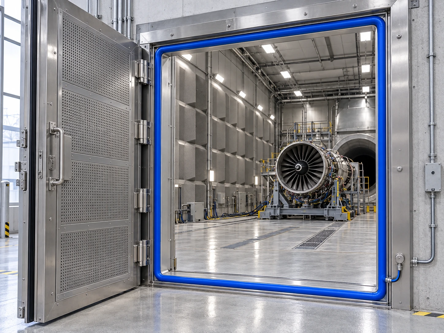
Seal fitted to a jet engine test cell door frame
AEROSPACE
Controlled door sealing in test facilities.
Explore inflatable seal and mounting options that provide contact around access door frames in jet engine test cells.
Explore the equipment, the joint where the seal works and manufacturing options for your application.
Enlarge image ↗Seal location: Fixed access-door frame of the ground-test chamber
01 / EQUIPMENT AND PURPOSE
Jet engine ground-test cells
Perimeter sealing at the test chamber access door.
A ground-test cell supports engine testing within a controlled facility. The large access door opens for engine handling and maintenance and is mechanically secured during testing.
The inflatable seal works between the access door and fixed test-cell frame. The illustrated loop belongs to that door joint; it is not a component fitted to the engine fan or air intake.
Benefits of the seal
Enclosing the joint. Helps limit unwanted air passage around the access door.
Wide service access. The vented profile releases the clearance required for door movement.
Controlled operating sequence. Closed and locked door status, seal pressure and venting are considered together.
Our manufacturing solution
We manufacture custom inflatable seals for this type of equipment. We assess the section, closed-loop dimensions, corner radii and air inlet arrangement against your drawing, and select the material for the temperature, product contact and cleaning conditions.
Selection and installation details
Provide test-cell pressure differentials and acoustic targets.
Measure door rigidity, lock positions and the perimeter gap.
Define material, traceability and testing requirements for the ground-test equipment at project outset.
Images are representative application designs, not photographs of customer installations. The final profile, material and operating values are established during project review.
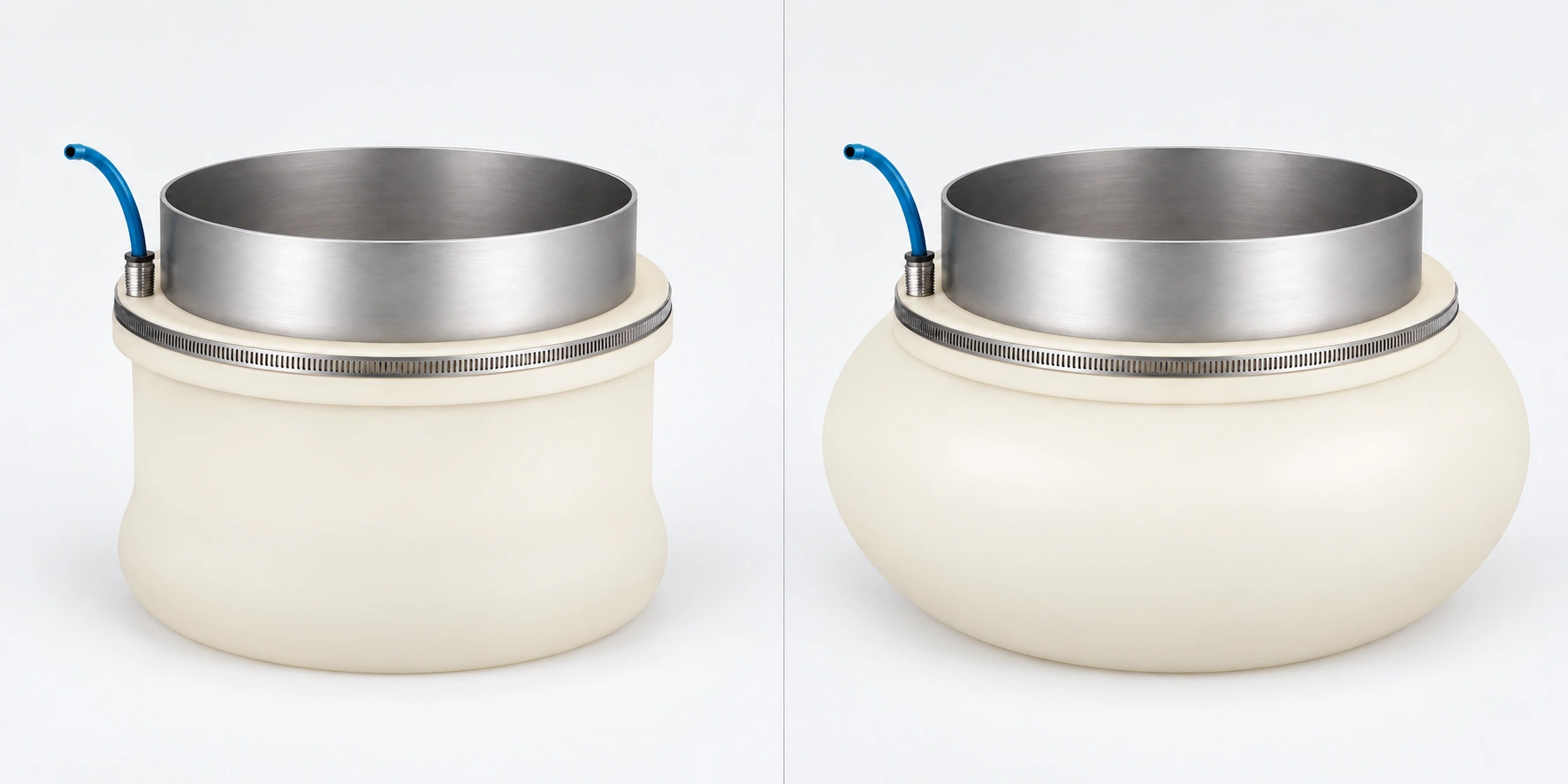
Left: deflated. Right: expanded with air. Mounting diameter, retaining band and air inlet stay the same; the flexible body expands outwards.
BIG BAG FILLING
Big bag filling sleeves: controlled contact at the inlet.
We manufacture custom inflatable filling sleeves for the spout-to-bag neck connection. Fitting when deflated, establishing contact with air and releasing after venting are stages of the same sleeve.
How the filling sleeve works, its benefits and applications
See the seal close up, explore how it contacts the bag inlet and compare dust escape at an open connection. Machine examples show where the seal is used.
Enlarge image ↗Seal location: Between the outside of the filling spout and the bag filling neck
01 / SEAL AND CONNECTION
Big bag filling sleeve
Controlled circumferential contact at the bag inlet, with an open central product passage.
The sleeve works between the outside of the filling spout and the inlet of an FIBC or a suitable necked sack. Inflation establishes circumferential contact; venting allows a bag change. Product passes through the open centre into the bag.
The sleeve mounting bore is matched to the spout outside diameter. The bag neck is placed over the deflated sleeve; air pressure expands the flexible body outwards against the bag inlet. Filling stops before the air is vented and the bag is released. Product passes through the open central tube; the sleeve does not support the bag weight.
Benefits of the seal
Helps reduce dust escape. Circumferential contact helps limit product escaping to the surroundings at the filling connection.
Easier bag changes. Venting relaxes the sleeve so the bag inlet can be fitted or removed.
Accommodates inlet variation. A correctly selected flexible body can accommodate limited variations in bag neck dimensions.
Our production for this application
We manufacture broad inflatable filling sleeves to suit your spout outside diameter, bag inlet and mounting arrangement. The air connection is positioned for accessible maintenance and protection from movement.
The bag inlet connection, step by step
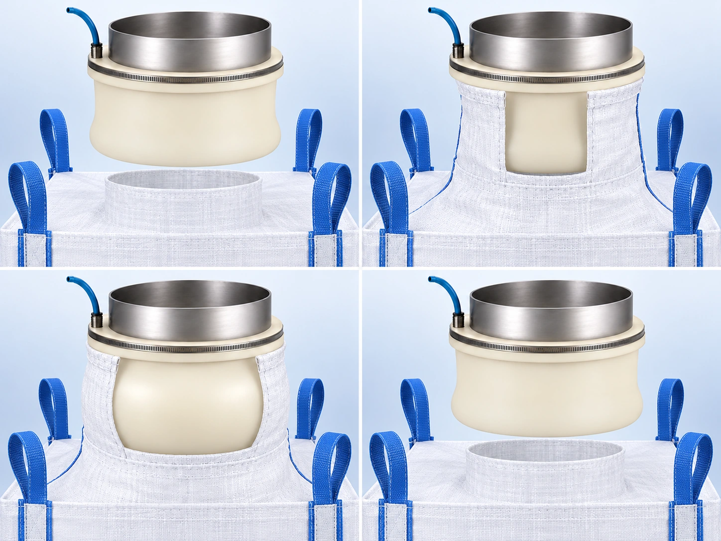
Four-loop FIBC with a central filling neck. The fabric opening is an illustrative cutaway showing sleeve contact; it is not an opening in the real bag.
01 / Prepare the connection
With the sleeve deflated, centre the FIBC inlet below the head. Hooks and/or a platform support the bag weight.
02 / Fit the inlet
Place the neck over the sleeve without wrinkles. Keep the retaining band and air connection accessible above the inlet.
03 / Inflate and fill
Establish circumferential contact with air. Confirm the connection before filling; product passes through the open central path.
04 / Stop, vent and release
Stop product feed first. Vent the sleeve; remove the relaxed inlet and discharge the bag using its handling arrangement.
What can happen at an open inlet gap?
Escaping dust, product loss and contamination of the work area.
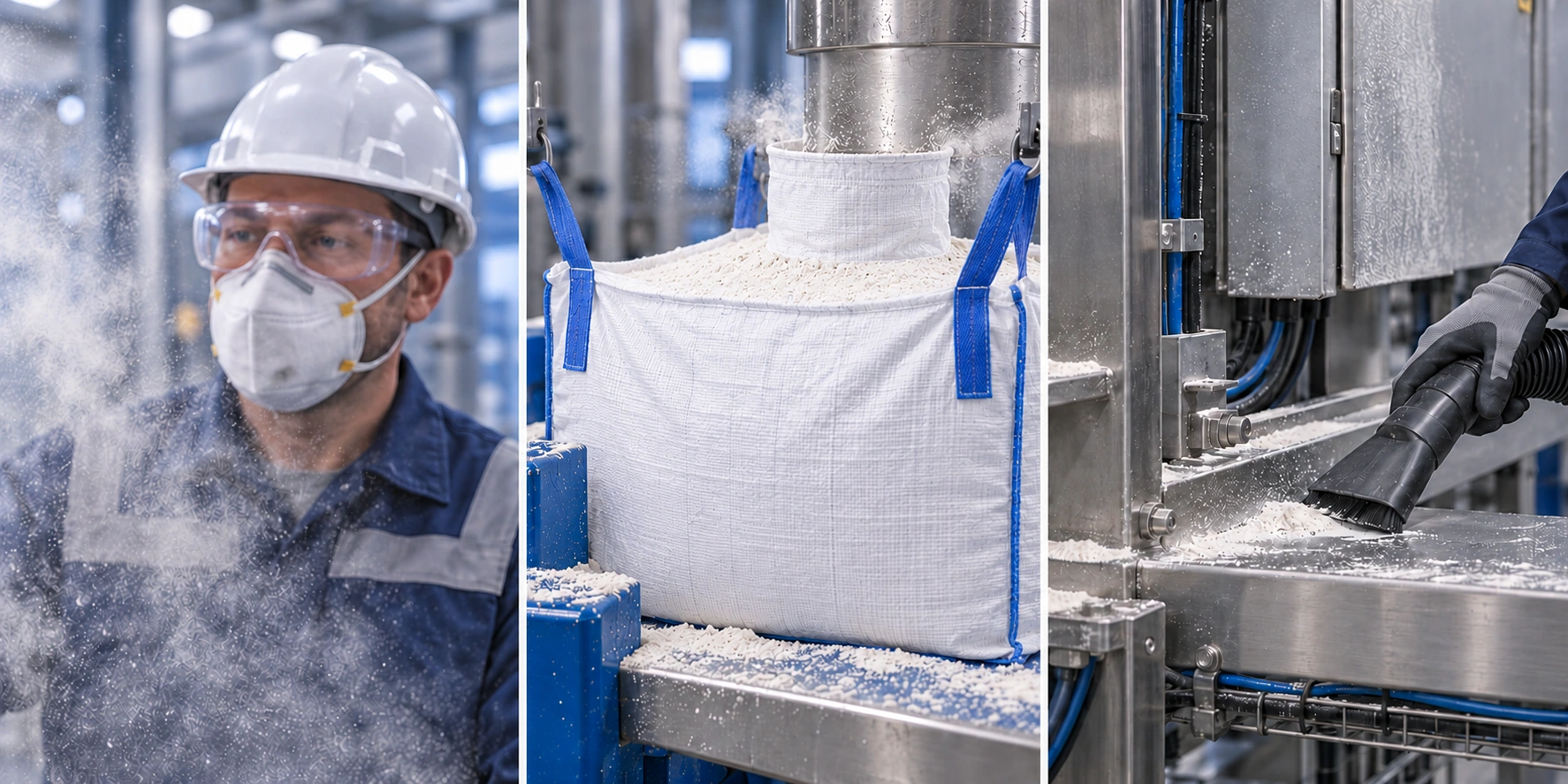
Left: dust escape at an open filling connection. Right: circumferential bag-inlet contact with an inflatable sleeve. This is illustrative, not a measured performance result.
Open connection
The gap between the spout and bag neck can provide a path for powder to escape into the surrounding work area.
Sleeve contact
A correctly sized sleeve expands outwards against the inlet, helping reduce dust escape at this connection.
Dust near the breathing zone, escaped product and removal of powder deposited on equipment surfaces.
Worker exposure
Depending on dust type, amount and duration of exposure, respiratory problems or eye and skin irritation may occur. Assess the actual product and workplace exposure.
Product escaping before it enters the bag can settle on the shoulder, platform or floor. Whether it can be recovered depends on the process conditions.
Cleaning and contamination
Deposits require cleaning of equipment and packaging surfaces. Transfer to nearby products is considered in hygiene and cross-contamination assessment.
The filling sleeve is one sealing component at the connection. Assess it together with dust extraction, ventilation, cleaning and appropriate personal protective equipment.
Selection and installation details
Fit the bag → inflate the sleeve → start filling → stop filling → vent the sleeve → release the bag.
Sleeve pressure and cycle times depend on the application; bag-body inflation and dust extraction are separate systems.
Bag weight is carried by the lifting hooks and/or the support platform.
Confirm the connection and bag position before filling; do not release the bag before filling has stopped.
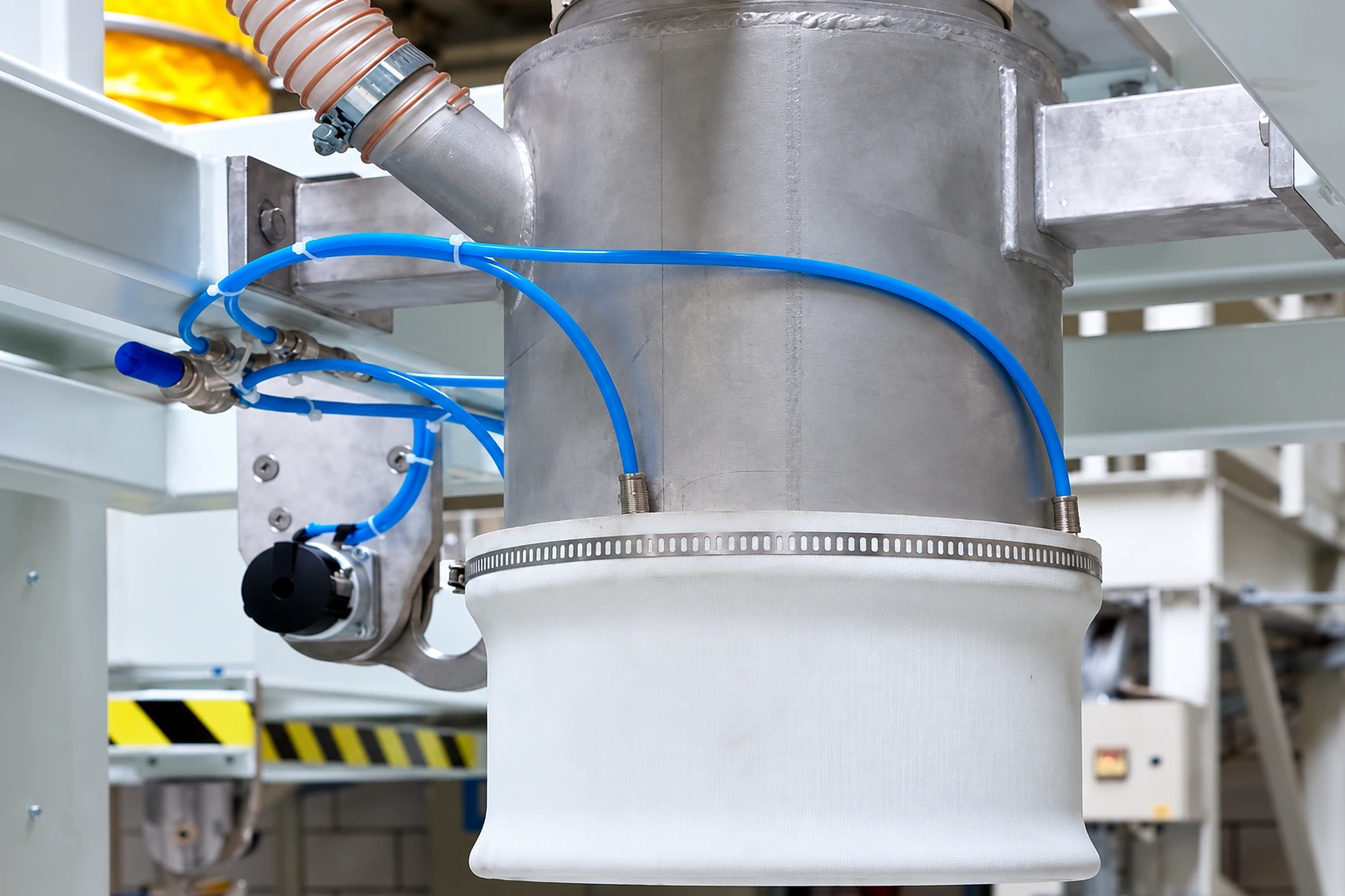
Enlarge image ↗Seal location: At the bag filling neck around the central filling spout
02 / SEAL AND CONNECTION
Filling sleeve at a single head
Sealing at the big bag inlet, independently of the bag support structure.
The sleeve at a single filling head is selected for the spout outside diameter and bag inlet. Contact length, retaining band and air inlet position are matched to the existing head. Hooks and/or a support platform carry the bag load.
The sleeve sits on the outside of the filling spout. The bag neck is fitted over it and the flexible body is inflated to contact the inlet circumference. The lifting arrangement and platform carry the bag; the filling sleeve is not a load-bearing suspension.
Benefits of the seal
Dust control at the connection. Reducing the inlet gap supports more controlled filling.
Orderly bag changes. The deflated state allows the filling neck to be released from the spout.
Adaptation to existing equipment. Suitable mounting geometry can support a new filling head or a replacement seal.
Our production for this application
We manufacture sleeves matched to your unit’s spout, bag neck and retaining arrangement. We assess the pneumatic line, lifting mechanism and operator access together.
Selection and installation details
The filling spout and bag inlet must be concentric.
Lifting-loop positions should not pull the filling neck sideways.
Weighing, filling cut-off and any dust extraction are assessed within the machine control arrangement.
Bag neck height and sleeve contact length are measured together.
Enlarge image ↗Seal location: At the spout-to-bag inlet connection on the filling head
03 / SEAL AND CONNECTION
Filling sleeves in conveyor lines
Repeatable connections in lines with sequential filling and bag discharge.
In a conveyor line, the sleeve works at the filling-head inlet. It establishes contact and releases during repeated filling and bag changes. Venting time and access for replacement are assessed against the line sequence.
The bag is secured at the filling position and its neck is placed over the deflated sleeve. Once inflation, filling and venting are complete, the bag is released to the handling system. The sleeve works at the filling head; the connection is released before conveyor movement.
Benefits of the seal
Organised cycles. Inflation and venting can be included in the bag-change sequence.
Repeatable connection. Correct centring and mounting help establish similar contact from bag to bag.
Maintenance access. Suitable air inlet and clamp positions make sleeve replacement easier.
Our production for this application
We assess the sleeve length, mounting diameter and pneumatic connection for the line’s filling head using your drawing. Hose routing is planned to avoid trapping during bag entry and discharge.
Selection and installation details
Do not start conveyor movement before releasing the bag connection.
Allow for sleeve inflation and venting times in the machine cycle.
Clamp and spout surfaces must not have sharp edges that damage the flexible body.
Provide access for cleaning and sleeve replacement.
Enlarge image ↗Seal location: Around each station’s own filling spout and bag neck
04 / SEAL AND CONNECTION
Independent sleeves at two heads
Independent inflatable sleeve connections at two separate filling heads.
Each of the two filling heads uses its own sleeve. Matching heads may share a seal geometry; different dimensions require separate parts. Inflation and venting are assessed independently at each connection.
Each sleeve works at its own bag inlet. Inflation and venting are controlled separately according to bag position and filling status. Changing a bag at one head must not release the connection at the other head.
Benefits of the seal
Independent connections. Each bag neck has its own contact and release sequence.
Flexible operating sequence. Bag preparation and filling can alternate where the machine design permits.
Standard maintenance parts. Matching heads can share a sleeve geometry to simplify spare-part management.
Our production for this application
We assess the spout and bag dimensions at each head, preparing shared sleeve geometry for matching heads or separate geometry where needed. Air inlet directions are planned around each station’s movement envelope.
Selection and installation details
Confirm bag position and filling connection separately at each station.
Arrange air lines and control valves so the stations do not interfere with each other.
Product routing and filling cut-off in a shared supply depend on the machine design.
Check installation and maintenance space for both heads.
Enlarge image ↗Seal location: Around the perimeter of the follower plate travelling inside the drum
05 / SEAL AND CONNECTION
Drum follower-plate seal
A follower-plate seal providing controlled contact with the drum’s inner wall.
For viscous products, this seal works between the follower-plate perimeter and the drum bore. Its mounting geometry differs from a filling sleeve: perimeter contact is maintained as the plate follows the product level.
The circumferential inflatable seal works between the follower-plate edge and the drum wall. Inflation expands it outwards against the wall, helping maintain perimeter contact as the plate follows the product level. The seal is vented in accordance with the machine’s plate-lifting sequence before removal.
Benefits of the seal
Circumferential contact. Helps limit the gap between the plate edge and the drum.
Reduced product loss. A suitable plate and seal arrangement can help reduce product remaining on the wall.
Drum changeover. Controlled venting helps release the plate and prepare for a new drum.
Our production for this application
We manufacture closed-loop inflatable seals to suit your drum bore, follower plate and groove. We assess product compatibility, wall friction, cleaning conditions and protection of the air inlet throughout the plate’s travel.
Left: follower plate before entry. Right: the perimeter seal contacts the drum bore. The opening in the drum wall is an illustrative cutaway.
Selection and installation details
Check drum bore, ovality and the condition of the internal wall.
The follower plate must travel centrally; the seal is not a mechanical centring device.
Plan pumping, plate movement, venting and any pressure equalisation within the machine’s own operating sequence.
Seal pressure, plate travel and elastomer friction are determined for the application.
Images illustrate the product and its applications; cutaways reveal the contact interface. Final dimensions, material and operating conditions are determined for your application.
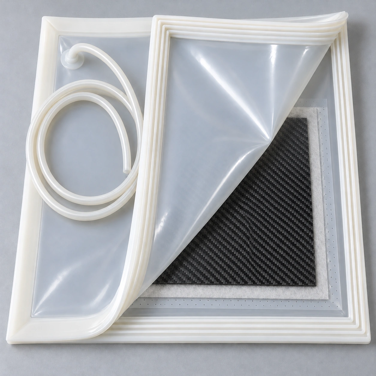
Product construction: flexible membrane, internal mating tracks and direct hose connection.
Silicone Vacuum Bags
Reusable silicone vacuum bags for glass lamination.
Explore flexible bag solutions for air evacuation during glass lamination. The working area, closure allowance and hose position are selected for your production arrangement.
Glass lamination
Decorative laminated glass
Composite assessment
What we assess when selecting a bag
Usable internal dimensions and glass-stack height
Process temperature, dwell time and vacuum conditions
Product construction: flexible membrane, internal mating tracks and direct hose connection.
Silicone Vacuum Bags
What is a silicone vacuum bag?
A silicone vacuum bag is a flexible enclosure that creates a closed working volume around a part. The vacuum line draws air out of this volume. The resulting pressure difference brings the membrane towards the enclosed stack. In glass lamination, the bag helps evacuate air around the glass and interlayer assembly. With a suitable material and process, the bag can be prepared for further production cycles.
Glass lamination
Decorative laminated glass
Composite process assessment
Smooth outside, interlocking tracks inside
The illustrated model consists of two flexible silicone sheets. The outward-facing surface of the white perimeter profile is smooth; the interlocking tracks are on the opposing inner faces. The parallel lines visible along the opened edge belong to this mating closure. Alignment through the corners, clean tracks and complete perimeter engagement matter when maintaining vacuum.
Silicone hose connected directly to the surface
The flexible hose connects directly to a silicone mounting base on the bag surface. Hose diameter, length and outlet position are assessed against the vacuum system, workbench and oven arrangement. For heated processes, the membrane, hose and connection region must be assessed together, including exposure time.
GLASS LAMINATION AND VACUUM PROCESSING
Applications of silicone vacuum bags
The bag perimeter remains the same while the enclosed part and auxiliary materials change with the application. These illustrations explain the product and example arrangements.
Glass application: the assembly sits inside the working area without touching the closure profile.
01 / Silicone Vacuum Bags
Silicone vacuum bags for glass lamination
Controlled air evacuation around the glass assembly.
Glass sheets and the chosen lamination interlayer are placed within the usable area. Once the bag is closed, air is evacuated through the vacuum connection. For EVA or other interlayers, the vacuum sequence and heating cycle follow the interlayer supplier’s process instructions. The bag is one component of the production arrangement: bonding and finished-glass quality also depend on the interlayer, preparation and thermal cycle.
Positioning the glass stack
Measure the glass width, length and total stack height. Allow perimeter clearance for the closure band and air passage. Prevent sharp corners from loading the membrane, the hose from being trapped under the glass and the evacuation path from closing. Connection number and position are assessed so the vacuum reaches the assembly.
The brown component represents PTFE-coated glass-fibre mesh between the outside glass surface and the bag.
02 / Silicone Vacuum Bags
What does PTFE-coated breather mesh do?
An auxiliary material that provides an air path between glass and bag.
PTFE-coated glass-fibre mesh uses its open structure to support air movement from around the glass towards the vacuum outlet. Appropriate placement can also help reduce direct bag contact with glass edges. This mesh is not a bonding interlayer. It is not placed between glass bonding faces as an adhesive or decorative lamination layer.
Assess the mesh and bag together
Mesh cleanliness, size and positioning affect the evacuation path. Check for wrinkles, thick overlaps and blocked routes to the outlet. Assess the mesh and edge protection against surface marking, process temperature and bag operating conditions.
Composite application example. The auxiliary layers shown are not an approved process recipe or specified layup sequence.
03 / Silicone Vacuum Bags
Assessment for carbon-fibre and composite processing
A vacuum bag selected alongside the part geometry and resin system.
Reusable silicone vacuum bags can also be assessed for suitable composite processes. Vacuum helps compact a layup and evacuate air. Flat panels, shaped tools and parts with different heights do not necessarily require the same bag geometry. Compatibility between the carbon fibre, resin, release materials and silicone bag is established for the application.
Process-specific consumables
Release film, peel ply and breather materials perform different functions. Their selection and sequence depend on the manufacturing method. Resin infusion, prepreg and wet layup do not share a single universal stack. Resin contact, cure temperature and part shape must be reviewed before confirming suitability of this bag for a composite process.
GLASS LAMINATION AND VACUUM PROCESSING
How does a silicone vacuum bag work?
Air is drawn out of the enclosure. Each stage of the production cycle is arranged around the bag, part and process conditions.
01
Prepare the part
Clean the work surface and mating tracks. Place the glass or part inside the usable area. Prepare the required breather and release materials to suit the defined process.
02
Engage the inner tracks
Align the mating tracks around the full perimeter, including corners. Keep dust, mesh, folded film and part edges out of the closure. Check that the hose is not pinched.
03
Check the vacuum
Evacuate the bag and perform the defined leak check. Once vacuum stability is confirmed, proceed with the approved heating cycle if required. Monitor vacuum and temperature throughout processing.
04
Cool and prepare for reuse
Complete the process-specific cooling and pressure equalisation steps before opening. Remove the part, then inspect the membrane, corners and hose base before the next cycle.
Benefits of a bag selected for the process
Repeated use
A suitable material and maintenance routine allow the same bag to be used over further cycles. Service life depends on thermal exposure, contact conditions and mechanical handling.
Visible positioning
A transparent or translucent membrane makes it easier to visually check the part and auxiliary material positions inside the bag.
Application-specific sizing
Working area, perimeter allowance and hose outlet are planned together against the existing workbench and production arrangement.
GLASS LAMINATION AND VACUUM PROCESSING
Selecting a custom-size silicone vacuum bag
Overall width and length alone are not enough to assess an order. Part size, closure clearance and operating conditions are considered together. A drawing or photograph of the existing bag helps clarify the arrangement.
Selecting a custom-size silicone vacuum bag
Information to share
Why it matters
Usable internal width × length
Defines the clear area for the part, auxiliary materials and air path; it differs from overall dimensions.
Part or glass-stack height
Used to assess whether the membrane covers the assembly without loading the closure.
Oven and workbench arrangement
Determines overall clearance, handling layout, shelf spacing and hose routing.
Peak temperature and dwell time
Supports material assessment for the silicone membrane, hose and connection region in the same cycle.
Vacuum conditions and connections
Target vacuum, pump arrangement, hose diameter and connection number are assessed together.
Interlayer, resin and cleaning method
Required for contact and chemical compatibility assessment.
Cycle frequency and existing issues
Clarifies reuse expectations, leak locations and the maintenance routine.
Vacuum leaks, cleaning and service life
If vacuum cannot be maintained, inspect the closure for contamination or incomplete engagement, corner folds, pinched hoses and membrane cuts. The connection line and pump arrangement also form part of the assessment. Bubbles or bonding defects in glass do not alone establish a bag fault: interlayer storage, surface preparation and the heating cycle also need consideration.
Prepare the bag after each cycle using a cleaning method compatible with its surface. Remove residue from the tracks without scraping them with sharp tools. Store the bag away from cutting surfaces without crushing the profile. Assess visible damage and recurring leaks before further production.
Frequently asked questions about silicone vacuum bags
Is a silicone vacuum bag the same as single-use bagging film?
No. The product shown has two silicone sheets and an internal perimeter closure that can be opened and closed again. Disposable bagging film is a different consumable with a different sealing arrangement.
Are there closure tracks on the outside surface?
The illustrated model has a smooth outside surface. The parallel mating tracks are on the opposing inner sheet faces and become visible when the bag is opened.
Are overall dimensions and usable area the same?
No. Overall dimensions include the perimeter profile and closing allowance. Measure the clear internal area available for the glass or part separately.
Can one bag be used with every glass lamination interlayer?
Suitability depends on the interlayer, temperature, exposure time and contact conditions. Share the supplier’s process data for the intended EVA or other interlayer.
Does the brown mesh go between the glass sheets?
The PTFE-coated breather mesh shown is positioned between the outside glass surface and the silicone bag. It does not replace the bonding interlayer.
What temperature can a silicone vacuum bag withstand?
There is no single temperature value for every silicone bag. Material, hose, connection region and time at temperature are assessed together; suitable operating values are established for the application.
What information is needed for a quotation?
Share usable width and length, stack height, oven layout, peak temperature and dwell time, vacuum arrangement, interlayer or resin, and a drawing or photograph of the existing bag.
Images are representative product and application designs. Final dimensions, material, connections and operating values are established through application review.
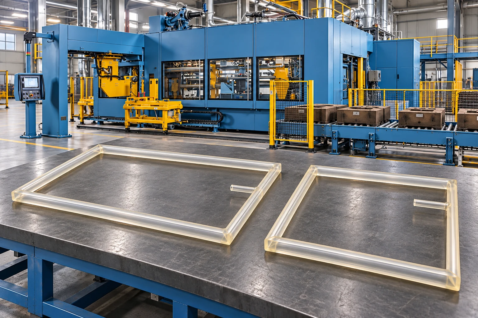
Polyurethane seal examples with different frame proportions for foundry and moulding systems.
Polyurethane Inflatable Seals
Controlled sealing for foundry and moulding systems.
Explore polyurethane inflatable seals for automatic green sand moulding lines and large-frame equipment. Frame dimensions, groove geometry and air connections are assessed together with the operating cycle of your machine.
Green sand moulding lines
Foundry equipment
Large-frame systems
What we assess for seal selection
✓Frame dimensions, groove section and corner geometry
✓Contact gap, surface movement and cycle frequency
✓Air supply, temperature and operating environment
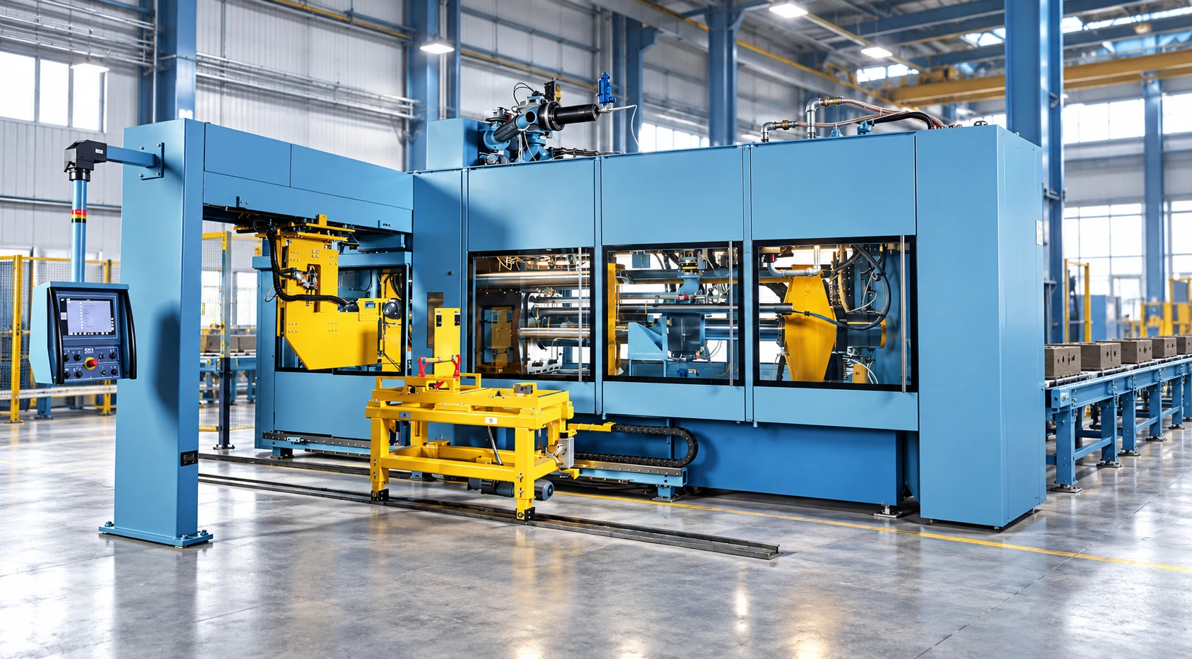
Automatic moulding line: seal placement is determined by machine geometry and the operating cycle.
FOUNDRY AND MOULDING
Controlled contact around large frames
A polyurethane inflatable seal expands when air enters its hollow profile, bringing it into contact with the mating surface. In automatic green sand moulding equipment, the installation is assessed against machine movement, surface tolerances and groove geometry for repeated operating cycles.
Why consider polyurethane?
Polyurethane can be considered where flexibility and mechanical durability are assessed together. The compound and profile are selected according to the contact medium, temperature, wear conditions and cycle frequency. Operating pressure and temperature limits are established for each project.
Inflate, make contact, deflate
01
Controlled air supply
Air enters the hollow profile through its air connection. Supply and exhaust are coordinated with the machine sequence.
02
Surface contact
The profile expands towards the mating surface. The contact gap, surface tolerances and frame corners are assessed together for consistent contact.
03
Exhaust and movement
Air is exhausted before the equipment opens or moves. The seal and groove are checked in preparation for the next cycle.
Frame dimensions and air connections for your application
For wide rectangular, elongated rectangular or near-square frames, overall dimensions, profile section and corner geometry are specified together. Catalogue examples show a flat inner face, a gently convex outer face and an inward-facing air connection. The final geometry is assessed against the mounting groove.
Information needed for polyurethane seal selection
Information to provide
Purpose
Frame and groove dimensions
Define inner and outer dimensions, groove section, corner radii and available installation space.
Contact gap and movement
Assess expansion direction, surface tolerances and the opening and closing cycle.
Environment and air supply
Review actual seal temperature, contact medium, air pressure and exhaust arrangement together.
Drawing and existing seal photographs
Confirm connection position, existing installation and replacement requirements.
Installation and care
Keep the mounting groove clean and install the seal without twisting it or straining the air connection. Initial operation and maintenance checks follow the machine manufacturer’s instructions. Cuts, wear, connection damage or uneven contact should be assessed before the next operating cycle.
You can change your optional cookie choices at any time.
Essential Cookies
Support basic website functions and remember your choices.
Analytics Cookies
Allow Google Analytics 4 to measure visits and Microsoft Clarity to analyse page interactions, heatmaps and session recordings. These services load only when analytics cookies are allowed.
Marketing Cookies
Allow Hostinger Reach to load its optional marketing and newsletter features.

 Enlarge image ↗
 Enlarge image ↗
 Enlarge image ↗
 Enlarge image ↗
 Enlarge image ↗